My Multi Site Ad Lab End To End
The Challenge
I wanted to simulate a multi-site Active Directory installation I had coming up. From the inter-site WAN connections through to the AD Sites and Services topology configuration.
As a fan of VMWare VSphere and with little experience of Hyper-V beyond conversations, I figured this was an opportunity to familiarise myself with that technology too.
Assumptions
Since I’d prefer to keep focused on the intended simulation, I’m avoiding going into detail on the below, so previous knowledge and experience is assumed:
- Windows Server and networking setup.
- General Active Directory configuration.
You’ll also need a host computer with sufficient resources to handle the VMs we’ll create:
- 1x Windows Server 2019 Datacenter
- 2x Windows Server 2012 R2 Datacenter
- VyOS router
How I Did It
Gathering Resources
Windows Server DVD Images
I headed over to the Microsoft Evaluation Centre to get ISOs for Server 2019 and Server 2012 R2.
VyOS
To simulate the inter-site routing I decided to use an old favourite - the rolling release version of VyOS. The version I used for this lab was 1.3-rolling-202001160217.
Setting up the Lab
Enabling Hyper-V
Thanks to Docker Desktop, I already had the Hyper-V role and management tools installed, but if you want to switch it on real quick in Windows 10 Pro (assuming your system meets the relevant pre-requisites), you can use the following PowerShell commands:
Enable-WindowsOptionalFeature -FeatureName Microsoft-Hyper-V -Online -Verbose -All
Restart-Computer
Customising Hyper-V
Just for ease of use, I modified 2 settings in Hyper-V Manager for my lab:
Default VM and VHD locations - both set to (in my case) D:\VMs
Start Hyper-V Manager if it’s not already open.
![]()
Right-click the name of your computer in Hyper-V manager, and click Hyper-V Settings…
Change the default Virtual Machines and Virtual Hard Disks folders and click OK.

Windows Server Base VMs
Next I set up 2 VMs, one for Windows 2019 Datacenter and one for Server 2012 R2.
I won’t go into detail about the install process for Windows Server - that’s outside the scope of this guide - I’ll just touch on any non-default settings conducive to my intended lab scenario.
Quick summary of settings:
- Location: D:\VMs\[VM-Name]
- Virtual Machine Generation 2
- Network Connection: Default Switch (to allow downloading programs and updates)
- Virtual Hard Disk Size: 40GB
- Install an operating system from a bootable image file
Sidebar: Disabling Automatic Checkpoints
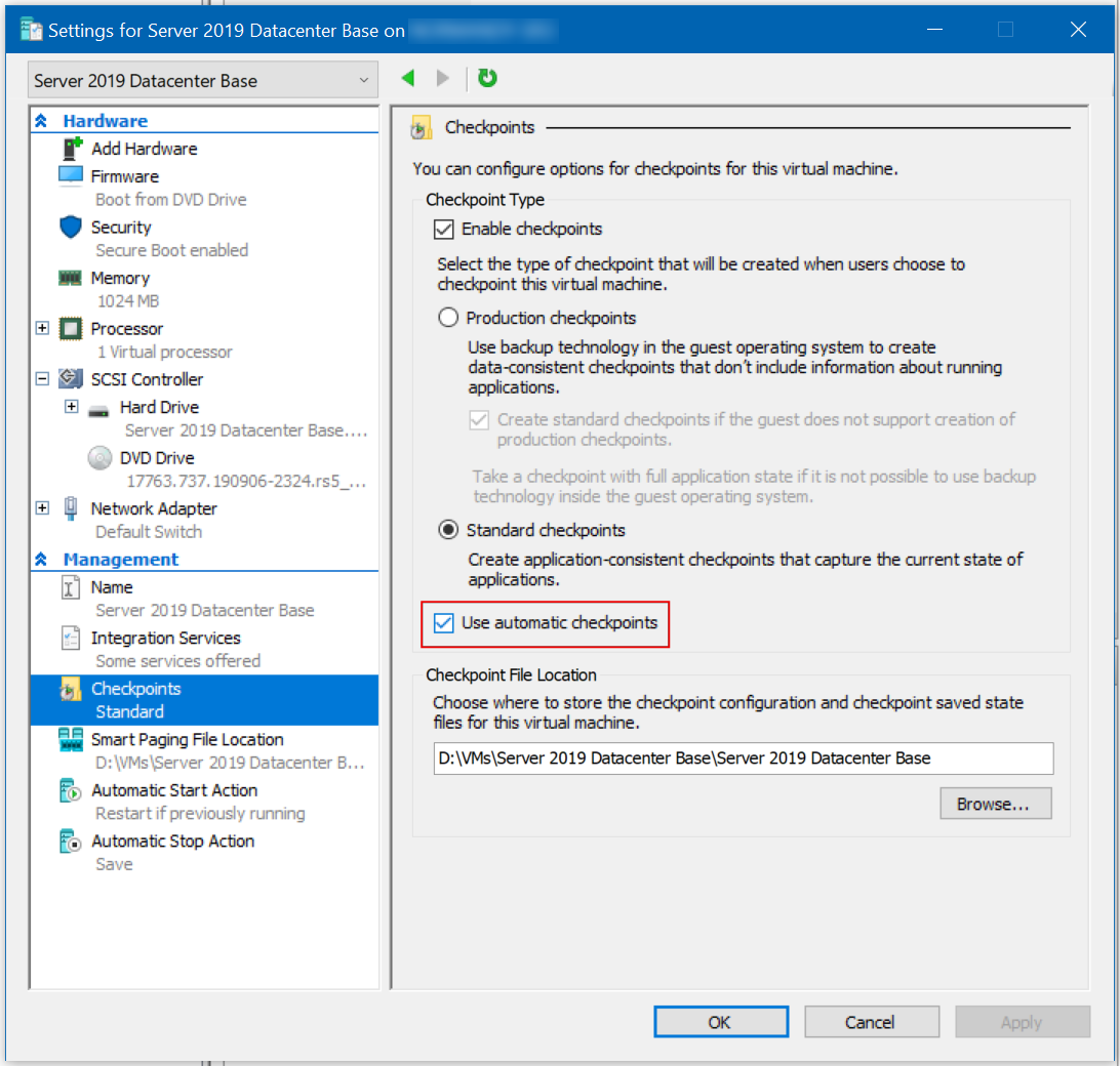
Normally, at least at time of writing, in Win 10 Pro 1909, all newly-created VMs have “Automatic Checkpoints” enabled by default, and there is no way to globally disable this, so you need to make sure to remember to go to the settings of each VM you create and disable the feature. You don’t have to disable it, but I prefer to choose when I make checkpoints, so I always disable the automatic ones before starting a VM.
Windows Server post-install steps
I ran all updates, added a few programs I like to have installed (such as VS Code, for testing and running scripts), then sysprepped both boxes, shutting them down in OOBE mode.
Next I found the VHDX files for the 2 base VMs, and set them to read-only, to make sure they couldn’t be changed after I started creating Differencing Disks with them as the source disks.
Setting up the Sites
Before setting up the actual VMs, I wanted to get the virtual sites and routing configured - so here’s how:
I made a plan! First I drew out my overall intention and the subnets I would use for each of the virtual sites, naming each for consistency and ease of identification throughout the process. The first drawing was very abstract, detail was added as the process continued.

Hyper-V Virtual Switches
In Hyper-V Manager, click Virtual Switches Manager… over on the shortcuts list on the right-hand-side.
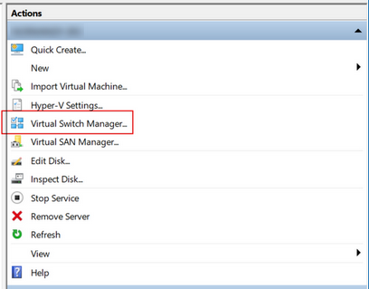
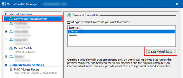
There’s already a “Default Switch” present - later, during VyOS configuration, that will be used as the Internet route.
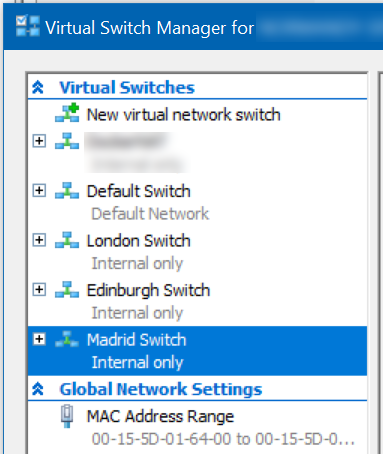
Click “New virtual network switch” at the top, click to highlight “Internal”, click “Create Virtual Switch”, name it after the site, leaving all other settings as default, then click “New virtual network switch” again, repeat the process until you have all the sites set up, then click OK.
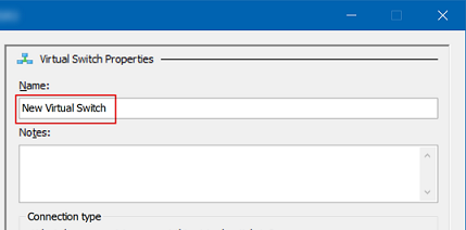
Ultimately, you should end up with a list of appropriately-named switches like this:
Configuring Host Ethernet Adapters - Important
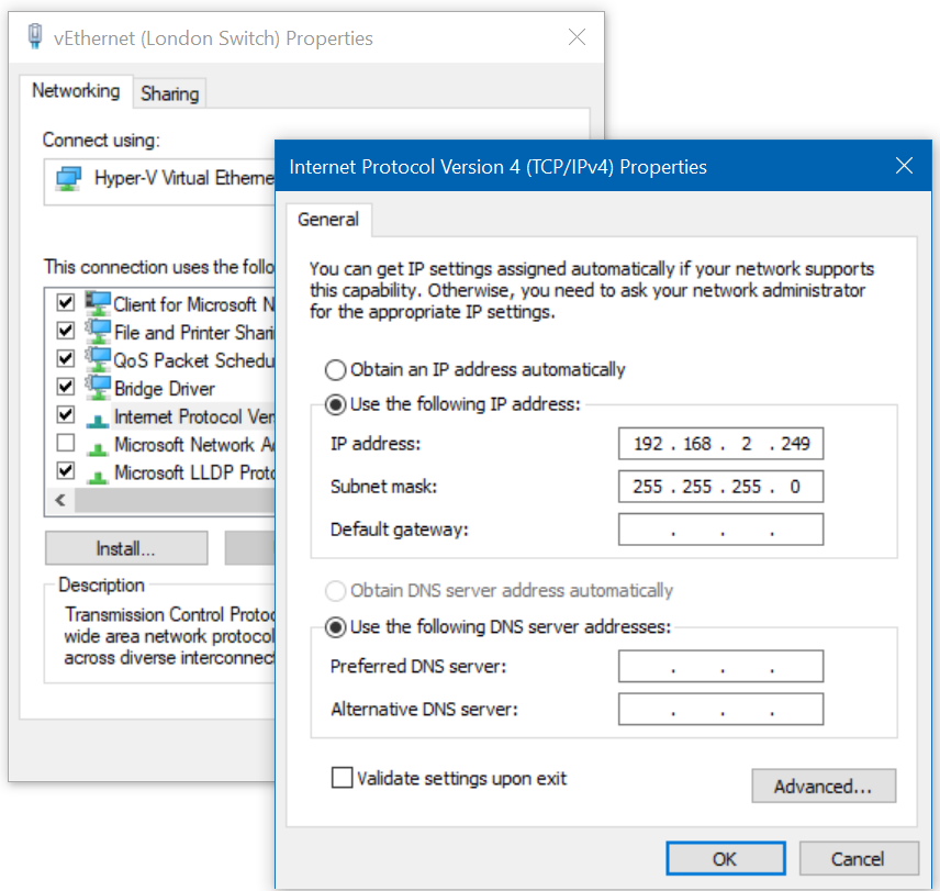
This is an important step - you want to statically configure an IP on each of the networks specified above on your host computer to make sure that the DHCP servers created later don’t cause some strange routing issues, and also to allow you to SSH into VyOS on any of its known static IP addresses.
Go to each of the appropriately-named Ethernet Adapters in Network and Sharing Center on your host PC, and give an
IP address of .249 on each of the respective subnets, making sure to leave Default Gateway and DNS Servers
empty. - For example, the ‘London’ Ethernet Adapter would be configured like this:
VyOS
Next I set up VyOS to handle the inter-site routing.
VM Setup
Back in Hyper-V Manager, create a new VM, observing the below non-default options.
Quick summary of settings:
- Location: D:\VMs\[VM-Name]
- Virtual Machine Generation 1
- Startup Memory: 512MB
- Uncheck “Use Dynamic Memory for this virtual machine” (if you don’t, VyOS seems to consume all available system memory over time)
- Network Connection: Default Switch (to allow downloading programs and updates)
- Virtual Hard Disk Size: 2GB
- Install an operating system from a bootable image file
Adding Network Adapters
After the New Virtual Machine wizard is finished, right-click the VyOS VM and click Settings…
Click Add Hardware, then choose Network Adapter and click Add:
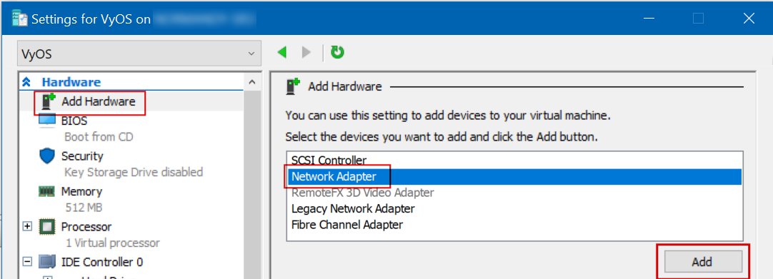
From the Virtual Switch drop-down, choose the Virtual Switch you want the Network Adapter connected to.
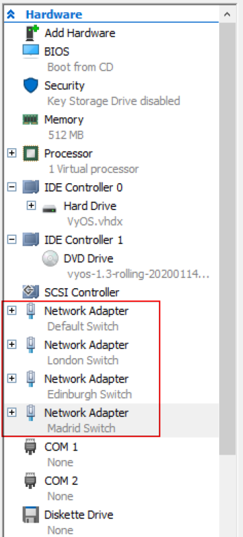
Repeat this process until you have added a Network Adapter and connected it to each of the named sites. In this case, London, Edinburgh and Madrid.
Click Apply. Your VyOS hardware summary should look similar to this:
Leave this Settings window for VyOS open - you’ll need some information from it when you set up the ethernet adapters inside VyOS.
Booting the VyOS installer
Start the VM and open its console.
Click in the window and press enter to choose “Live (amd64-vyos)” - if you don’t, it will start by default anyway.
Go back to the Settings window for VyOS and click refresh at the top.

Next, expand the Network Adapters for all 4 switches (include the Default one), then highlight Advanced Features, updating the network topology drawing with the last 2 digits of the MAC address shown - this will make it easier to identify the ethernet adapters and name them in VyOS shortly.
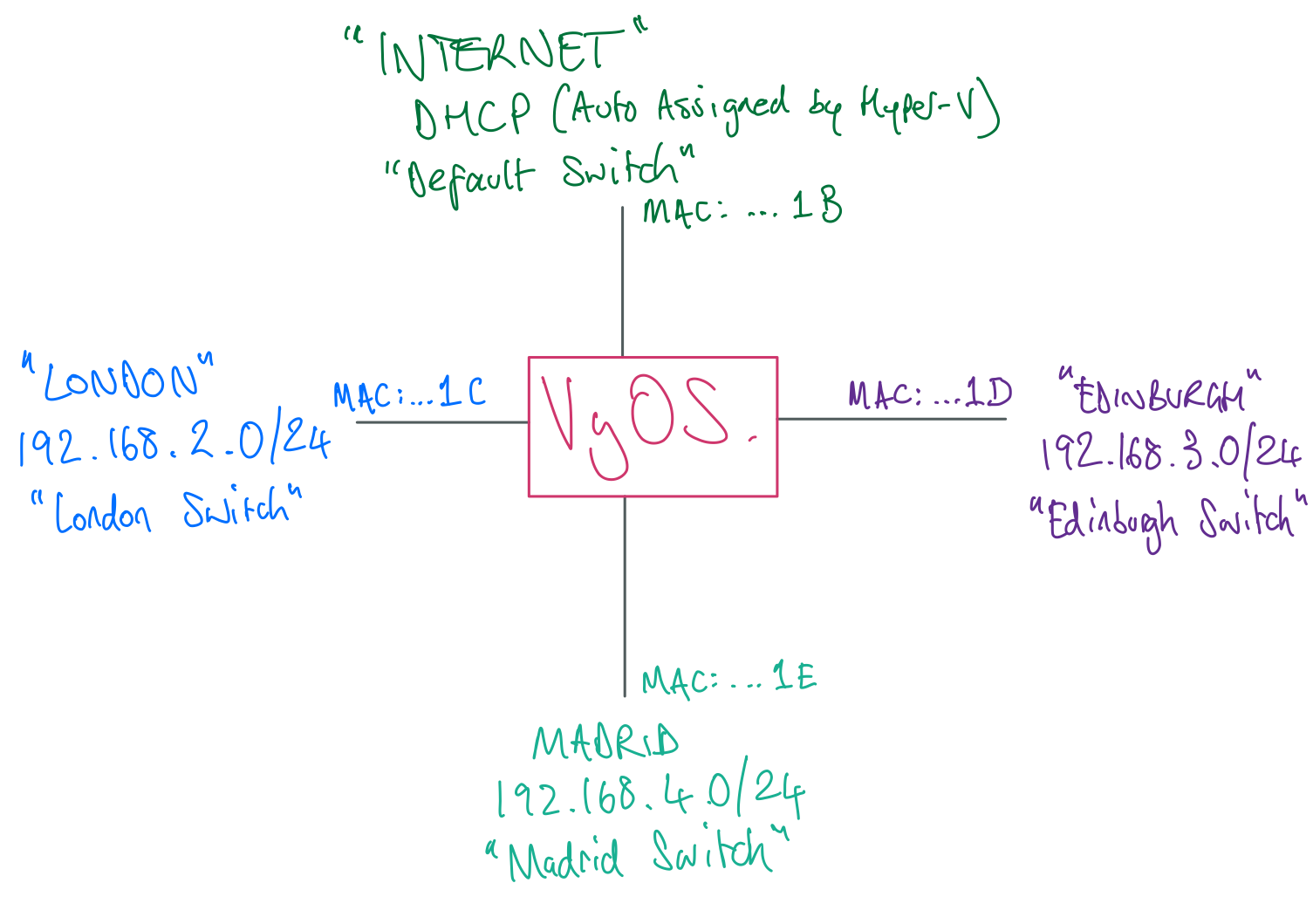
Now close the VyOS Settings window.
Logging in and installing VyOS
Back in the VyOS console, log in with vyos as both the user name and the password.
Type install image and press ENTER
Yes you would like to continue ENTER
Partition Auto ENTER
Install the image on sda ENTER
Continue yes ENTER
Partition size - just press ENTER to accept the default.
Image name - again, accept the default by pressing ENTER
Accept the default configuration file with ENTER
Create a good password for the vyos administrator account and press ENTER - be aware that the keyboard layout
in the VyOS console is EN-US.
Accept the default for the GRUB boot partition with ENTER
Type poweroff and hit ENTER, then type y and hit ENTER to shut down VyOS.
Bring up the Settings window for VyOS again, then click the DVD Drive entry and change the Media to “None” and click OK.
Start VyOS again and open the console.
This time you should see a longer list of boot options - choose the first one ending in “(KVM console)”
Configuring VyOS
Login with vyos and the password you specified earlier.
At the vyos@vyos:~$ prompt, type configure and press ENTER - the prompt will change to vyos@vyos#
Network Interfaces
Type show interfaces and press ENTER - you will get a list of the ethernet interfaces and their MAC addresses.
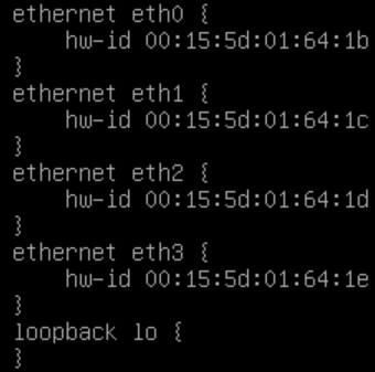
Take this opportunity to update your network topology diagram.
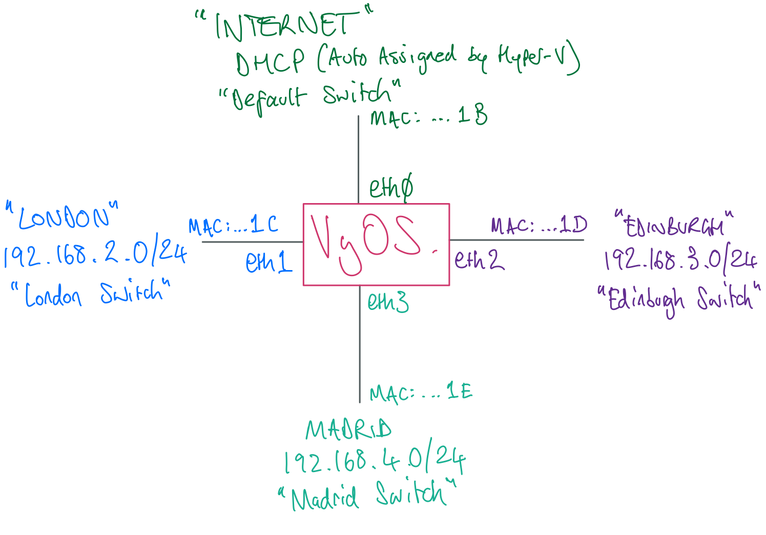
Keeping that handy, you can now start configuring the ethernet interfaces.
Use the below sequence of commands to set up the interfaces with meaningful descriptions and IP addresses. After this initial setup, you’ll enable the SSH server and connect to VyOS using PuTTY (or similar) which will allow you to copy/paste commands, saving some time.
For some ease, you can use the up-arrow cursor key to bring up previous commands and just modify the bits you need.
Also for ease, VyOS supports tab auto-completion, so you can hit TAB for hints if you can’t remember a sub-command,
or type in a few letters and press TAB to save typing.
set interfaces ethernet eth0 description 'Internet'
set interfaces ethernet eth0 address dhcp
commit
save
NOTE: commit will commit any changes you’ve made to the current session, but if you reboot the router, they will
not be saved. save actually writes those changes to the config. This is useful to know if you want to test something out with an option to revert if you made a mistake.
If you type ping 8.8.8.8 and press ENTER you should get replies, meaning you’ve connected VyOS to the internet
successfully.
Pressing CTRL+C will stop the pings.
Now set up the remaining interfaces as below - this will give VyOS an IP ending in .250 on each network.
set interfaces ethernet eth1 description 'London'
set interfaces ethernet eth1 address 192.168.2.250/24
set interfaces ethernet eth2 description 'Edinburgh'
set interfaces ethernet eth2 address 192.168.3.250/24
set interfaces ethernet eth3 description 'Madrid'
set interfaces ethernet eth3 address 192.168.4.250/24
commit
save
If you type show interfaces and hit ENTER again, you should see something like this:
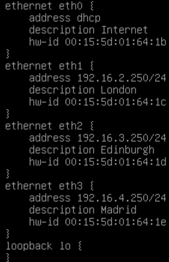
Connect via SSH
Now you can prepare VyOS to accept incoming connections on SSH.
Type the following commands:
set service ssh port 22
commit
save
Bring up your Network Adapters on your local Windows machine, and pick one of the adapters named after one of the sites you’ve created.
Assign it an IP address on the appropriate subnet for that site (like 192.168.2.249 for London, for example), don’t bother with Default Gateway or DNS servers.
Open up your preferred TTY program (PuTTY in my case) and connect to the .250 address of VyOS on the subnet you configured an address for in the previous step.
You may need to click Yes to a security thumbprint dialog. Obviously we would never be so ignorant of security in production.
Enjoy the ability to resize the console window to your heart’s content(!)
Log in to VyOS with your username and password - once again note that when you configured the password for VyOS initially, it was in an EN-US keyboard layout.
Type configure at the vyos@vyos:~$ prompt and press ENTER
Now you can copy and paste commands in to VyOS.
General VyOS Settings
Next some general settings such as the router’s name, time zone and domain name, and DNS servers for internet name resolution.
I named mine rtr01 with a domain name matching the lab AD domain I would be creating.
set system domain-name lab.bakersfoundry.co.uk
set system host-name rtr01
set system name-server 8.8.8.8
set system name-server 8.8.4.4
set system time-zone Europe/London
commit
save
At this point, you should get a response if you type (for example) ping www.microsoft.com which shows that
name resolution is working from VyOS.
I used Google’s DNS servers, and since I’m based in England, I chose Europe/London as my time zone.
Setting up Internet Access Routing with NAT
Now to give VyOS some rules for how to handle internet-bound packets from the various subnets it’s connected to.
set nat source rule 10 outbound-interface eth0
set nat source rule 10 source address 192.168.2.0/24
set nat source rule 10 translation address masquerade
set nat source rule 11 outbound-interface eth0
set nat source rule 11 source address 192.168.3.0/24
set nat source rule 11 translation address masquerade
set nat source rule 12 outbound-interface eth0
set nat source rule 12 source address 192.168.4.0/24
set nat source rule 12 translation address masquerade
commit
save
outbound-interface is telling VyOS that any packets not routable to any of its ‘known’ networks from the source
networks designated here, should be routed out via eth0 (our Internet adapter).
Masquerade meaning that the router substitutes its own internet-facing IP address for the IP address of the
device sending the packet, along with a randomly-assigned port number so that reply packets can be sent back to
the correct originating device by the router.
The rule x numbers simply designate in which order VyOS will process them - there is a range from 1-9999, VyOS’
very helpful documentation suggests keeping 1:1 NAT rules at the top (rule 1 onwards) and general traffic rules
beneath those, since VyOS will obey the first match found in the order of rules.
Setting up DNS Services
Because the sites will start with no DNS servers, I will enable the DNS server service, configure dns forwarders, allow DNS requests from those sites, and instruct Vyos to listen on its IP addresses in each site.
set service dns forwarding system
set service dns forwarding name-server 8.8.8.8
set service dns forwarding name-server 8.8.4.4
set service dns forwarding allow-from 192.168.2.0/24
set service dns forwarding allow-from 192.168.3.0/24
set service dns forwarding allow-from 192.168.4.0/24
set service dns forwarding listen-address 192.168.2.250
set service dns forwarding listen-address 192.168.3.250
set service dns forwarding listen-address 192.168.4.250
commit
save
At this point, each site has internet access, and inter-site routing will be working.
Setting up Active Directory Sites and Services
Differencing Disks
Earlier I touched on the creation of Base Images for the Servers. Assuming they’re all done, updated and sysprepped , here’s how to build VMs based on Differencing Disks, using the read-only VHDX files from the Base Image VMs as source, or “parent” disks. Which will make up the VMs (aside from the Windows 10 Enterprise “Laptop”) you will set up in the various sites.
Creating the Differencing Disks
- In Hyper-V Manager, click New, then Hard Disk…
- Click Next to get past the “Welcome” screen
-
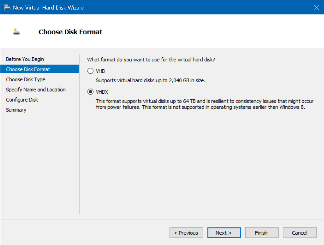
Choose the same disk type as the Base VMs (I used VHDX), click Next
-
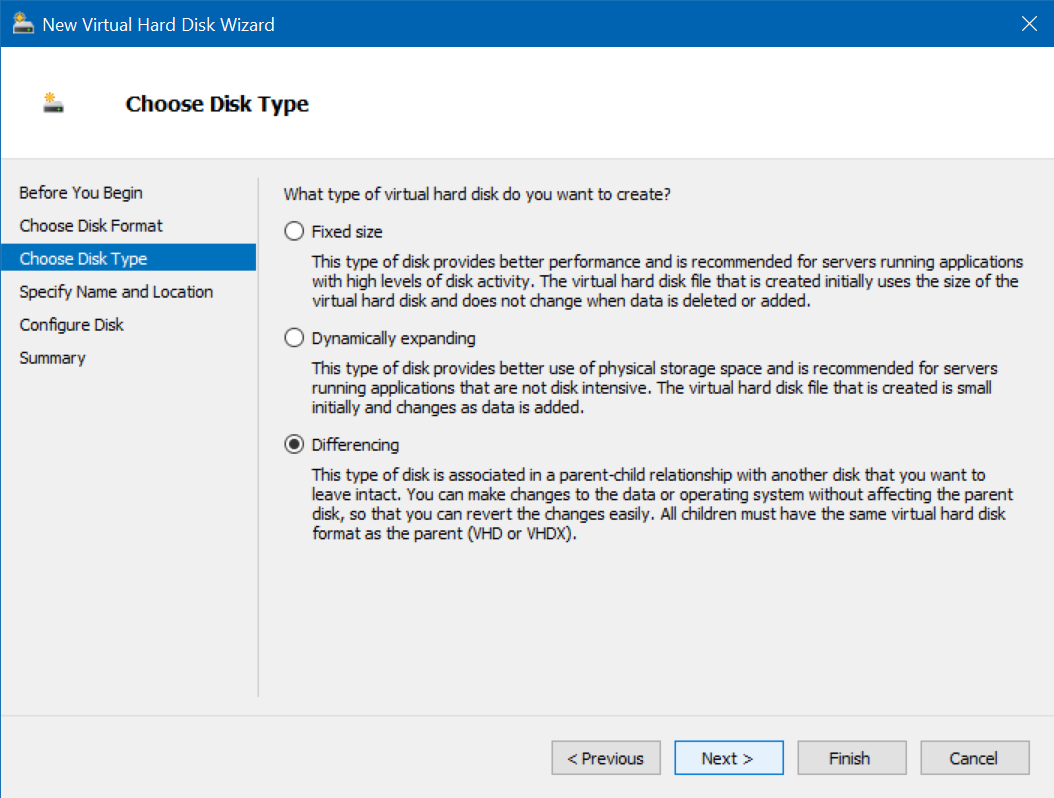
Choose Differencing, click Next
-
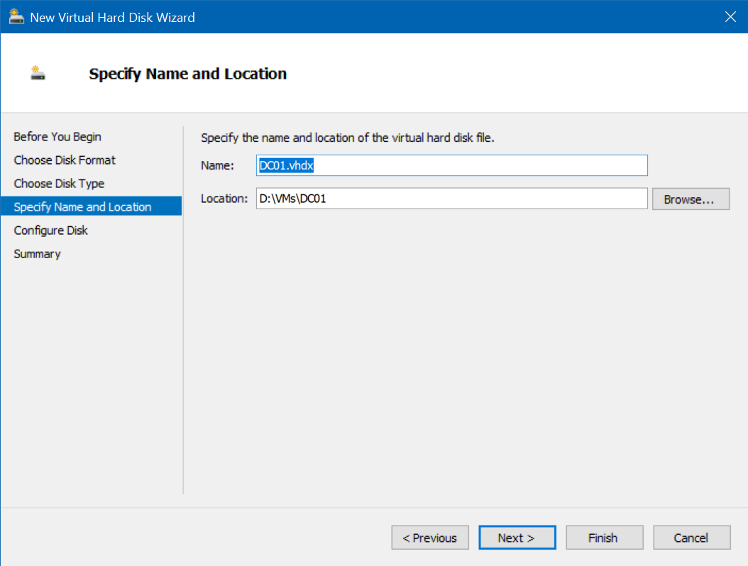
In name and location of New Disk, name the disk and folder after the intended VM (for example DC01)
-
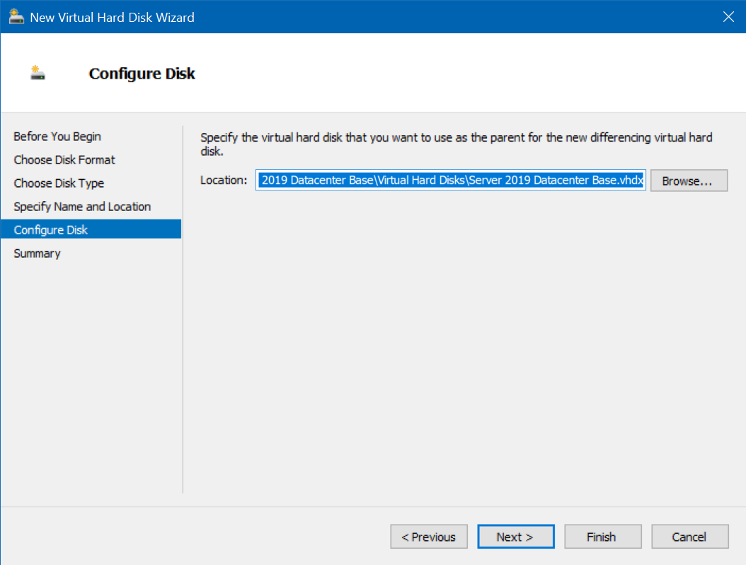
In the Parent disk selection, find the VHDX file for the appropriate version of Windows you’re installing - 2019 in this case, click Next then Finish
- Repeat this process for all the intended VMs
Creating VMs from the Differencing Disks
To do this, follow the normal procedure for creating a new Virtual Machine, but on the “Connect Virtual Hard Disk” step, choose “Use an existing virtual hard disk” and select the appropriate disk for the VM you’re building.
NOTE: Make sure the Virtual Machine Generation matches the original Base VM.
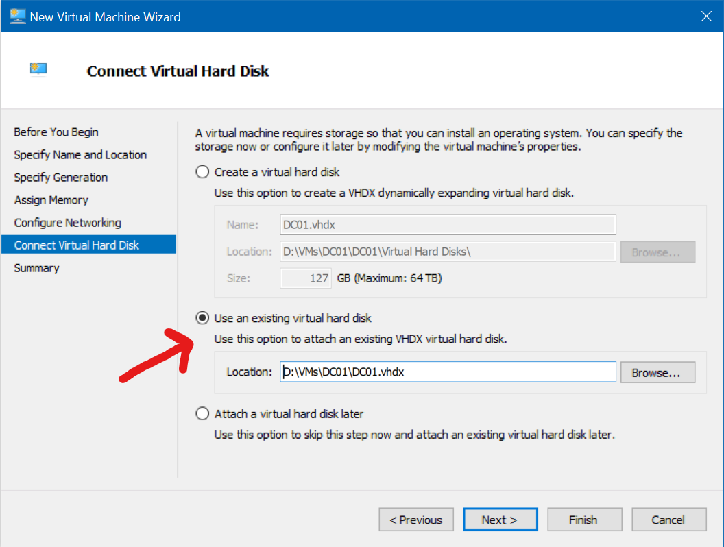
Repeat the process to fulfill the requirements for the lab…
Pre-requisites
- Server 2019 Datacenter Domain Controller in London site.
- Virtual Switch: London
- Name: DC01
- Domain Controller
- Forest and Domain Functional Level: Server 2012 R2
- FQDN: lab.domain.com
- IP: 192.168.2.1
- Additional Services: DHCP
- Server 2012 Datacenter server in Edinburgh site.
- Virtual Switch: Edinburgh
- Name: RODC01
- IP: 192.168.3.1
- Additional Services: DHCP
- Server 2012 Datacenter server in Madrid site.
- Virtual Switch: Madrid
- Name: RODC02
- IP: 192.168.4.1
- Additional Services: DHCP
The Edinburgh and Madrid servers should have no AD services installed at this point.
Site Configuration
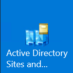
On the London Site Windows 2019 Datacenter Server, open Active Directory Sites & Services.
Naming the London Site
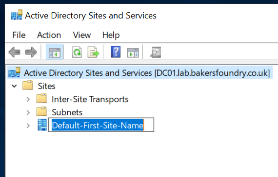
Expand the Sites node in the left pane, then right-click Default-First-Site-Name, click Rename and change it to
London
Creating a Subnet
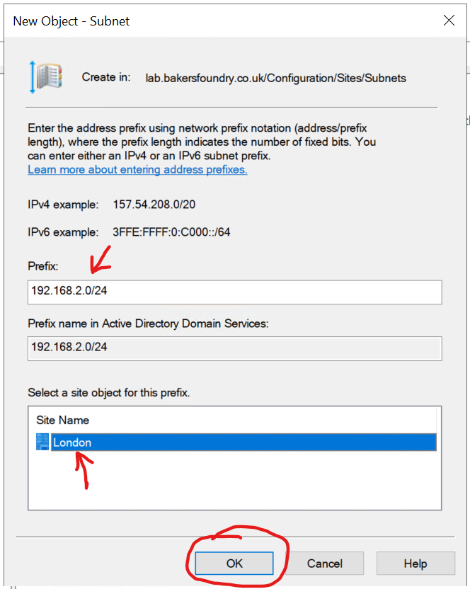
Right-click the Subnets node, then click New Subnet...
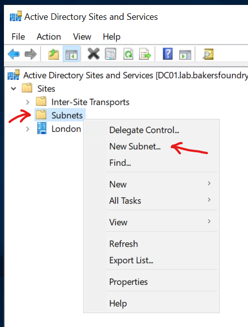
Enter the Subnet Prefix and length for the London site (192.168.2.0/24), then click London from the list(!) of available sites, then click Ok.
Creating Additional Sites
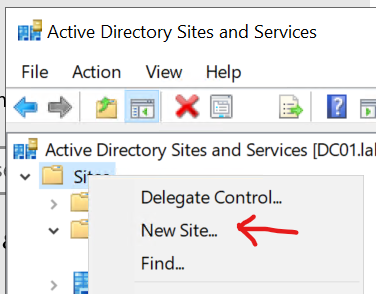
Right-click the Sites node in the left-hand pane, then click New Site...
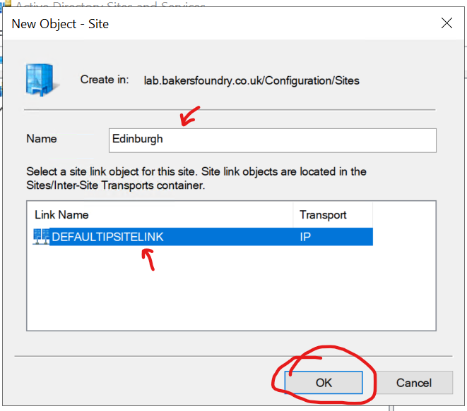
Name the site Edinburgh, and select the DEFAULTIPSITELINK and click Ok. You’ll change the Site Link later.
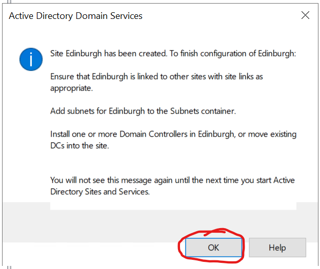
You will see a message with next steps from Active Directory Domain Services, you can just click OK to this.
Repeat the above process for Madrid.
Next use the ‘Creating a Subnet’ instructions above to create corresponding Subnets for Edinburgh (192.168.3.0/24) and Madrid (192.168.4.0/24).
Your Sites and Services window should look like the below. Subnets matching Sites as appropriate.

Active Directory has now been told that any device which joins the Domain in a given subnet is in the corresponding physical location, so it will find the geographically closest Domain Controller to handle security operations such as checking credentials on login.
The Site Transports you create next will tell Active Directory how it can physically replicate data to the RODCs created in the next section.
Inter-Site Transports
Expand the Inter-Site Transports node, then click the IP node.
Right-click the DEFAULTIPSITELINK entry, click Delete, then click Yes.
Right-click in the empty space, then click New Site Link...
Enter the name LondonEdinburghVPN, then click to highlight London and Edinburgh, then click Add
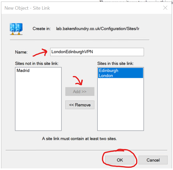
Repeat the above to create a link called LondonMadridVPN containing London and Madrid.
Double-click each of the newly-created Site Links, change the Replication Interval to 15 minutes and click Ok.
Afterwards, you should see the below in the Inter-Site Transports list.

The Cost metric is not relevant to you in this Lab scenario - it’s intended for use as a weighting tool to allow
Active Directory to favour cheaper links over more expensive ones for Replication. Since this Lab is simulating an
always-on VPN connection, there’s no need to change anything.
Adding the Read-Only Domain Controllers
At this stage, you’ve created an Active Directory Site Replication Topology, so now it’s time to promote those Servers in Edinburgh and Madrid to Read-Only Domain Controllers in the respective Sites.
NOTE: Make sure to set the Servers’ Primary DNS to the IP of the DC01 in London (192.168.2.1) prior to promoting them to RODCs.
If you use the GUI method to promote the Servers to Domain Controllers, you should see that the Site field is automatically populated with the correct location, as below:
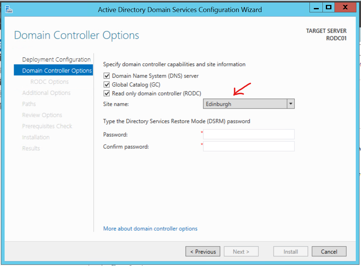
NOTE: Leave all the Read-Only Domain Controller options as default for this lab.
NOTE: You’ll need to Authorise the DHCP servers on the RODCs after the dcpromo operation is completed.
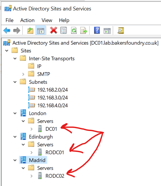
Afterwards, if you expand the Servers nodes in Active Directory Sites and Services under the 3 sites, you should see the Domain Controllers listed (you may need to refresh each site by first right-clicking the site name then clicking refresh):
Testing Domain Replication
Allowing Event Viewer connections through the Firewall - Important
To avoid some errors in the dcdiag process later, you’ll need to enable a rule in the Firewalls of the RODCs to
allow incoming RPC connections to Event Viewer.
Open up firewall.cpl and go to Advanced Settings, then Inbound Rules.
Scroll down to find Remote Event Log Management (RPC) and double-click it.
Tick the box to Enable the rule, go to the Scope tab and add the IP address for DC01 in London (192.168.2.1) to the Remote IP address list, then click OK.
Repeat this for both RODCs.
Manually starting a Replication
Open Active Directory Users and Computers on DC01 in London. Create an Organisational Unit called Standard Users.
Open Active Directory Sites and Services, click to expand the Edinburgh site, expand Servers, RODC01, then click on
NTDS Settings and in the right-hand pane, right-click RODC Connection (SYSVOL) and click Replicate Now and
click Ok on the following message.
Check in Active Directory Users and Computers on the Edinburgh site RODC01, making sure you are connected to the Edinburgh Domain Controller rather than DC01 in London (which it will do by default).
You should see the OU you created.
Repeat this process for Madrid.
DCDiag
On DC01 in London, open an Elevated Command Prompt.
Issue the following command:
dcdiag /e /f:".\desktop\dcdiag.txt"
You should find a notepad file on DC01’s desktop, showing successes in everything but DFSREvent tests and possibly some errors relating to Hard Drive Caching.
If you want a “straight answer” on whether replication is working, you can also use the below command:
dcdiag /e /test:replications
If you see this:
Directory Server Diagnosis

Performing initial setup:
   Trying to find home server...
   Home Server = DC01
   * Identified AD Forest.
   Done gathering initial info.

Doing initial required tests

   Testing server: London\DC01
      Starting test: Connectivity
         ......................... DC01 passed test Connectivity

   Testing server: Edinburgh\RODC01
      Starting test: Connectivity
         ......................... RODC01 passed test Connectivity

   Testing server: Madrid\RODC02
      Starting test: Connectivity
         ......................... RODC02 passed test Connectivity

Doing primary tests

   Testing server: London\DC01
      Starting test: Replications
         ......................... DC01 passed test Replications

   Testing server: Edinburgh\RODC01
      Starting test: Replications
         ......................... RODC01 passed test Replications

   Testing server: Madrid\RODC02
      Starting test: Replications
         ......................... RODC02 passed test Replications


   Running partition tests on : DomainDnsZones

   Running partition tests on : ForestDnsZones

   Running partition tests on : Schema

   Running partition tests on : Configuration

   Running partition tests on : lab

   Running enterprise tests on : lab.bakersfoundry.co.uk
You can be assured that replication is running as expected.
The End!
You have created a lab environment, simulating a multi-site organisation with VPN links between a Domain Controller and 2 branch office Read-Only Domain Controllers.
If you made it this far, well done! Now take a snapshot and start playing.
